
| Home | Sources Directory | News Releases | Calendar | Articles | | Contact | |
Current source

A current source is an electrical or electronic device that delivers or absorbs electric current. A current source is the dual of a voltage source. The term constant-current sink is sometimes used for sources fed from a negative voltage supply. Figure 1 shows a schematic for an ideal current source driving a resistor load.
Contents |
[edit] Ideal current sources
In circuit theory, an ideal current source is a circuit element where the current through it is independent of the voltage across it. It is a mathematical model, which real devices can only approach in performance. If the current through an ideal current source can be specified independently of any other variable in a circuit, it is called an independent current source. Conversely, if the current through an ideal current source is determined by some other voltage or current in a circuit, it is called a dependent or controlled current source. Symbols for these sources are shown in Figure 2.
 |
 |
| Voltage source | Current Source |
.svg) |
.svg) |
| Controlled Voltage Source | Controlled Current Source |
| Battery of cells | Single cell |
An independent current source with zero current is identical to an ideal open circuit. For this reason, the internal resistance of an ideal current source is infinite. The voltage across an ideal current source is completely determined by the circuit it is connected to. When connected to a short circuit, there is zero voltage and thus zero power delivered. When connected to a load resistance, the voltage across the source approaches infinity as the load resistance approaches infinity (an open circuit). Thus, an ideal current source, if such a thing existed in reality, could supply unlimited power and so would represent an unlimited source of energy.
No real current source is ideal (no unlimited energy sources exist) and all have a finite internal resistance (none can supply unlimited voltage). However, the internal resistance of a physical current source is effectively modeled in circuit analysis by combining a non-zero resistance in parallel with an ideal current source (the Norton equivalent circuit). The connection of an ideal open circuit to an ideal non-zero current source does not represent any physically realizable system.
[edit] Physical current sources
[edit] Resistor current source
The simplest current source consists of a voltage source in series with a resistor. The current available from such a source is given by the ratio of the voltage across the voltage source to the resistance of the resistor. For a nearly ideal current source, the value of this resistor should be very large but this implies that, for a specified current, the voltage source must be very large. Thus, efficiency is low (due to power loss in the resistor) and it is usually impractical to construct a 'good' current source this way. Nonetheless, it is often the case that such a circuit will provide adequate performance when the specified current and load resistance are small. For example, a 5 V voltage source in series with a 4.7 kilohm resistor will provide an approximately constant current of 1 mA (–5%) to a load resistance in the range of 50 to 450 ohm.
[edit] Active current sources
Active current sources have many important applications in electronic circuits. Current sources (current-stable resistors) are often used in place of ohmic resistors in analog integrated circuits to generate a current without causing attenuation at a point in the signal path to which the current source is attached. The collector of a bipolar transistor, the drain of a field effect transistor, or the plate of a vacuum tube naturally behave as current sources (or sinks) when properly connected to an external source of energy (such as a power supply) because the output impedance of these devices is naturally high when used in the current source configuration.
[edit] JFET and N-FET current source
A JFET can be made to act as a current source by tying its gate to its source. The current then flowing is the IDSS of the FET. These can be purchased with this connection already made and in this case the devices are called current regulator diodes or constant current diodes or current limiting diodes (CLD). An enhancement mode N channel MOSFET can be used in the circuits listed below.
[edit] Simple transistor current source

Figure 3 shows a typical constant current source (CCS). DZ1 is a zener diode which, when reverse biased (as shown in the circuit) has a constant voltage drop across it irrespective of the current flowing through it. Thus, as long as the zener current (IZ) is above a certain level (called holding current), the voltage across the zener diode (VZ) will be constant. Resistor R1 supplies the zener current and the base current (IB) of NPN transistor (Q1). The constant zener voltage is applied across the base of Q1 and emitter resistor R2. The operation of the circuit is as follows:
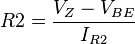
Voltage across R2 (VR2) is given by VZ - VBE, where VBE is the base-emitter drop of Q1. The emitter current of Q1 which is also the current through R2 is given by

Since VZ is constant and VBE is also (approximately) constant for a given temperature, it follows that VR2 is constant and hence IE is also constant. Due to transistor action, emitter current IE is very nearly equal to the collector current IC of the transistor (which in turn, is the current through the load). Thus, the load current is constant (neglecting the output resistance of the transistor due to the Early effect) and the circuit operates as a constant current source. As long as the temperature remains constant (or doesn't vary much), the load current will be independent of the supply voltage, R1 and the transistor's gain. R2 allows the load current to be set at any desirable value and is calculated by
 or
or 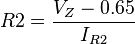 , since VBE is typically 0.65 V for a silicon device.[1]
(IR2 is also the emitter current and is assumed to be the same as the collector or required load current, provided hFE is sufficiently large). Resistance R1 at resistor R1 is calculated as
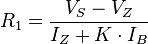 where, K = 1.2 to 2 (so that R1 is low enough to ensure adequate IB),
 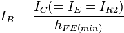 and hFE(min) is the lowest acceptable current gain for the particular transistor type being used.
A more common current source in integrated circuits is the current mirror.
[edit] Simple transistor current source with diode compensation

Temperature changes will change the output current delivered by the circuit of Figure 3 because VBE is sensitive to temperature. Temperature dependence can be compensated using the circuit of Figure 4 that includes a standard diode D (of the same semiconductor material as the transistor) in series with the Zener diode as shown in the image on the left. The diode drop (VD) tracks the VBE changes due to temperature and thus significantly counteracts temperature dependence of the CCS.
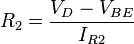
Resistance R2 is now calculated as

Since VD = VBE = 0.65 V,[2]
Therefore, 
(In practice VD is never exactly equal to VBE and hence it only suppresses the change in VBE rather than nulling it out.)
and R1 is calculated as
 (the compensating diode's forward voltage drop VD appears in the equation and is typically 0.65 V for silicon devices.[3])
This method is most effective for Zener diodes rated at 5.6 V or more. For breakdown diodes of less than 5.6 V, the compensating diode is usually not required because the breakdown mechanism is not as temperature dependent as it is in breakdown diodes above this voltage.
[edit] Simple transistor current source with LED

Another method is to replace the Zener diode with a light-emitting diode LED1 as shown in Figure 5. The LED voltage drop (VD) is now used to derive the constant voltage and also has the additional advantage of tracking (compensating) VBE changes due to temperature. R2 is calculated as
and R1 as
 , where ID is the LED current.
[edit] Feedback
Another common method is to use feedback to set the current and remove the dependence on the Vbe of the transistor. Figure 6 shows a very common approach using an op amp with the non-inverting input connected to a voltage source (such as the Zener in an above example) and the inverting input connected to the same node as the resistor and emitter of the transistor. This way the generated voltage is across the resistor, rather than both the resistor and transistor. (For details, see the article on the ideal op amp - the nullor.) The article on current mirror discusses another example of these so-called gain-boosted current mirrors.
[edit] Current mirror
Feedback is also used in the two-transistor current mirror with emitter degeneration. Feedback is a basic feature in some current mirrors using multiple transistors, such as the Widlar current source and the Wilson current source.
[edit] Other practical sources
In the case of opamp circuits sometimes it is desired to inject a precisely known current to the inverting input (as an offset of signal input for instance) and a resistor connected between the source voltage and the inverting input will approximate an ideal current source with value V/R.
[edit] Inductor type current source

Amongst other applications, the circuit of Figure 7 using the LM317 voltage regulator is used to present a source of constant current in Class E (switching) electronic amplifiers.
[edit] High voltage current sources
A Van de Graaff generator behaves as a current source because of its very high output voltage coupled with its very high output resistance and so it supplies the same few microamperes at any output voltage up to hundreds of thousands of volts (or even tens of megavolts) for large laboratory versions.
[edit] Current and voltage source comparison
Most sources of electrical energy (mains electricity, a battery, ...) are best modeled as voltage sources. Such sources provide constant voltage, which means that as long as the amount of current drawn from the source is within the source's capabilities, its output voltage stays constant. An ideal voltage source provides no energy when it is loaded by an open circuit (i.e. an infinite impedance), but approaches infinite power and current when the load resistance approaches zero (a short circuit). Such a theoretical device would have a zero ohm output impedance in series with the source. A real-world voltage source has a very low, but non-zero output impedance: often much less than 1 ohm.
Conversely, a current source provides a constant current, as long as the load connected to the source terminals has sufficiently low impedance. An ideal current source would provide no energy to a short circuit and approach infinite energy and voltage as the load resistance approaches infinity (an open circuit). An ideal current source has an infinite output impedance in parallel with the source. A real-world current source has a very high, but finite output impedance. In the case of transistor current sources, impedances of a few megohms (at DC) are typical.
An ideal current source cannot be connected to an ideal open circuit because this would create the paradox of running a constant, non-zero current (from the current source) through an element with a defined zero current (the open circuit). Nor can an ideal voltage source be connected to an ideal short circuit (R=0), since this would result a similar paradox of finite non zero voltage across an element with defined zero voltage (the short circuit).
Because no ideal sources of either variety exist (all real-world examples have finite and non-zero source impedance), any current source can be considered as a voltage source with the same source impedance and vice versa. These concepts are dealt with by Norton's and Thévenin's theorems.
[edit] See also
- Voltage-to-current converter
- Current mirror
- Iron-hydrogen resistor
- Widlar current source
- Wilson current source
- Current loop
- Welding power supply, a device used for arc welding, many of which are designed as constant current devices.
- Current sources and sinks
[edit] References and notes
- ^ The value for VBE varies logarithmically with current level: for more detail see diode modelling.
- ^ See above note on logarithmic current dependence.
- ^ See above note on logarithmic current dependence.
[edit] Further reading
- "Current Sources & Voltage References" Linden T. Harrison; Publ. Elsevier-Newnes 2005; 608-pages; ISBN 0-7506-7752-X
[edit] External links
|
SOURCES.COM is an online portal and directory for journalists, news media, researchers and anyone seeking experts, spokespersons, and reliable information resources. Use SOURCES.COM to find experts, media contacts, news releases, background information, scientists, officials, speakers, newsmakers, spokespeople, talk show guests, story ideas, research studies, databases, universities, associations and NGOs, businesses, government spokespeople. Indexing and search applications by Ulli Diemer and Chris DeFreitas.
For information about being included in SOURCES as a expert or spokesperson see the FAQ or use the online membership form. Check here for information about becoming an affiliate. For partnerships, content and applications, and domain name opportunities contact us.